
Boresighting: Configurations and In-Flight Applications
Itai Vishnia, CEO of PLX, Inc.
Michelle Hyers, Director of Engineering of PLX, Inc.
Martin Rost, Senior Optical Engineer of PLX, Inc.
PLX high-performance optical systems are renowned for performing under the harshest environmental conditions such as extreme temperature, combat and deep space while maintaining near-perfect accuracy over time. In the 1990s, PLX leveraged its space heritage, patented technologies, and proprietary processes to develop targeting verification systems that satisfied the most exacting defense specifications. Today, PLX continues to push the boundaries of boresighting and targeting systems, specifically with in-flight boresighting (as opposed to ground-based systems). With their exceptional stability, PLX’s boresighting systems have been repeatedly proven in the field, such as helicopter flight and battlefield conditions.
Review of Boresighting Verification Technology
PLX’s Boresighting Verification Technology dramatically enhances your targeting capabilities. Boresighting refers to the procedure of aligning hardware line-of-sight to an aiming device, or to the co-alignment of two or more optical axes, such as a laser and an imaging system. In military and aerospace terms, this can apply to applications such as weaponry, from small rifles to artillery, tank and aircraft fire control systems, or long-range cameras and laser/receivers mounted on satellites.
PLX’s boresighting verification technology utilizes their proprietary, high-accuracy, beam-delivery systems. This new capability enables you to verify the alignment of your hardware’s optical axis and your aiming device with sub-arcsecond accuracy. PLX can build these systems to operate with great stability, even under extremely harsh levels of vibration and shock encountered in military and aerospace applications. At PLX, we specialize in customizing our proprietary optical technology (as illustrated below) to meet challenging technical requirements within a wide range of applications.
 Lateral Transfer Hollow Periscope (LTHPTM)
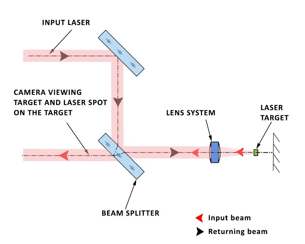
Figure 1.This is a schematic showing a long-range camera, such as an IR camera, which must be perfectly aligned to a laser designator.
In this application shown in Figure 1, the camera and the laser can be mounted on a turret that enables viewing in all possible coordinates in space. For the purpose of boresighting, the turret has a pre-determined position that enables the laser and the camera system to view the laser target through the boresighting system. The camera, focusing on a cross hair, must display the focused dot from the laser on the cross hair. Mechanical adjustment is required to tip and tilt the laser to bring the laser dot to the center of the cross hair. Alternately, this can be accomplished electronically. The camera captures a larger field of view than is displayed. The camera readout is adjusted to bring the laser dot to the center of the display.
PLX Lateral Transfer Hollow Retroreflector (LTHRTM) and Lateral Transfer Hollow Periscope (LTHPTM)
A device allowing two line-of-sights to be viewed together must be precision alignedand invariant with respect to environmental conditions. PLX offers various devices to meet these requirements. Two common PLX solutions for boresighting applications are the Lateral Transfer Hollow Retroreflector (LTHRTM), and the Lateral Transfer Hollow Periscope (LTHPTM). The LTHRTM consists of a flat mirror and roof mirror (two mirrors at 90° to each other), arranged so that the output is again offset and parallel to the input, but the direction of travel of the light has been reversed. An LTHRTM application example, wherein the LTHRTM further utilizes a beam-splitter in place of the flat mirror is shown in Figure 2. The LTHPTM consists of two mirrors arranged so that the output is offset from the input a fixed distance but is parallel to the input beam. In the case of a periscope, the light continues travelling in the same direction.

Figure 2. This schematic illustrates the same concept as Figure 1, but instead utilizing an invariant and highly stable Lateral Transfer Hollow Retroreflector (LTHRTM).
In order to achieve the alignment critical in boresighting, a Lateral Transfer Hollow Periscope (LTHPTM), with total beam deviation in the magnitude of single arcseconds, should be used. The accuracy of the LTHPTM is a critical requirement for the system, such that it must be maintained under the environmental condition in which the system is operated and throughout the lifetime of the instrument.
The LTHPTM and LTHRTM are invariant, high-accuracy monolithic optical tube assemblies that enable perfect beam delivery. In some embodiments, the tubes and the mirrors are made from low expansion glass such as Pyrex and Quartz, and, as such, are not sensitive to temperature changes. These assemblies utilize front surface reflection to enable high reflectance at all wavelengths, from UV to far IR. PLX has qualified these high precision invariant systems for applications involving harsh military conditions, such as helicopter battlefield conditions, and space vehicle launch.
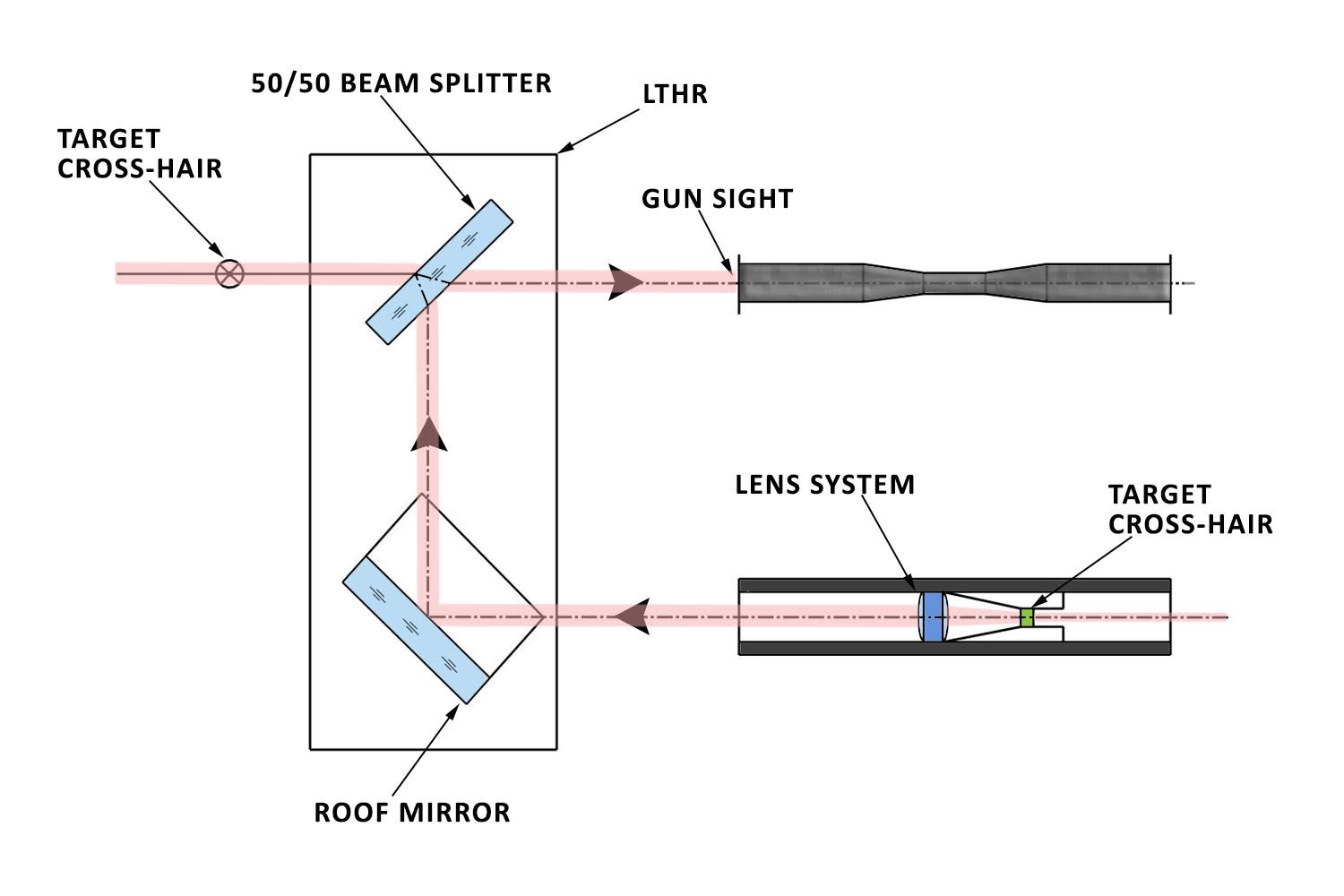
Figure 3. This schematic shows boresighting procedures between a gun barrel and a gunsight. This method of boresighting is as follows: a collimator that projects a cross hair target is inserted into the bore.The LTHRTM with a beam-splitter makes the cross hair target appear to be out in front of the gun sight. As described below, great accuracy is required between the inside diameter of the barrel and the outer diameter of the collimator.
For Figure 3, a unique version of PLX’s LTHRTM, equipped with a 50/50 beam-splitter on the flat mirror side is required. The LTHRTM is mounted such that the user can simultaneously view the crosshair from the collimator and the cross hair in the gunsight. The alignment procedure requires high-resolution mechanical means to tilt and tip the gunsight to a new position where the two cross hairs coincide with each other.
Utilizing PLX Rotary Movement Device (RMDTM)
In applications where more than one optical axis exists in a system, the PLX Rotary Movement Device (RMDTM) is recommended. The RMDTM enables a rotary connection between an LTHPTM, and LTHRTM or any combination thereof. Such combinations can be utilized in conjunction with the configurations shown in Figures 1, 2, and 3. The animation below shows the full range of motion of the Rotary Movement Device (RMDTM) that can be utilized for scanning through a large area.
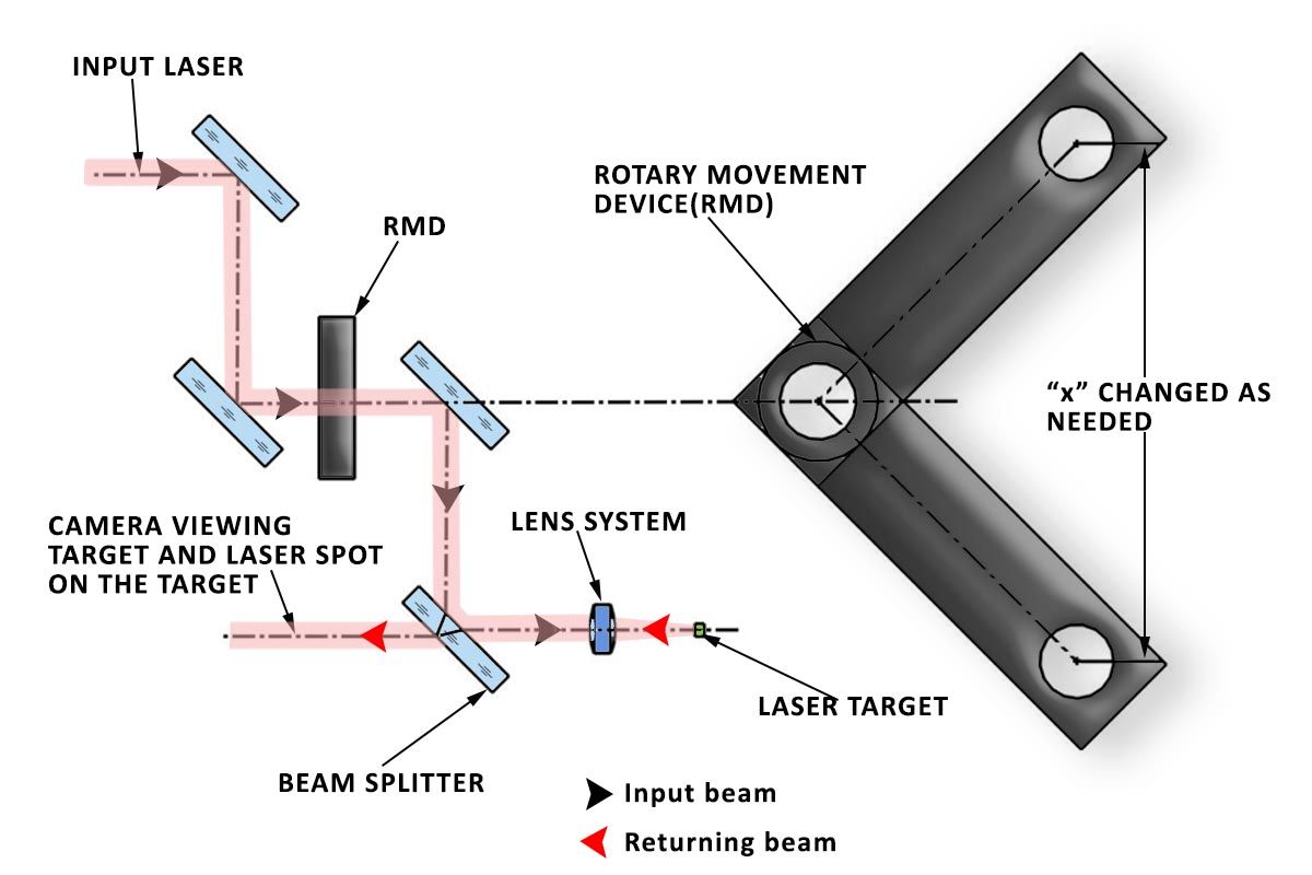
Figure 4. This illustration shows the configuration of Figure 1 utilizing an additional LTHPTM to enable variable distance of the optical axis. The distance “x” changes as a function of the angle between the devices, thus enabling an unlimited amount of optical axis on one plane. The RMDTM is supplied with locking mechanism to ensure proper position at any bore-sighting axis.
Figure 5. Animation GIF demonstrating the range of motion of the Rotary Movement Device (RMDTM) by PLX
Case Study: In-Flight Boresighting
PLX developed a Boresighting system in conjunction with Lockheed Martin for the Apache Helicopter (AH-64D and AH-64E). Deliveries for the Apache (AH-64D) began in 2005 after an extensive development program. The Boresighting system is designed to allow simultaneous viewing of multiple lines of sight. The module uses two LTHRTM assemblies configured in a rugged housing that provides up to one arc second parallelism under the most adverse conditions. The unit operates with extreme stability, even subjected to the harshest levels of vibration and shock, such as helicopter flight and battlefield conditions. To date, approximately two thousands of this particular boresighting system assembly have been delivered.

Figure 6. Image of the Apache Helicopter AH-64D/E, where PLX worked on the Boresighting system with Lockheed Martin.
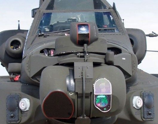
Figure 7.Front view of the Apache Helicopter AH-64D/E
What makes the Modernized Target Acquisition Designation Sight/Pilot Night Vision Sensor (M-TADS/PNVS) system unique is that the pilot and targeting systems can operate simultaneously, where the targeting system is divided into two parts Modernized Night Sensor Assembly (M-NSA) and Modernized Day Sensor (M-DSA).
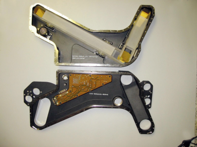
Figure 8. Image of the actual Boresighting system unit, with the two halves of the housing opened to show the two LTHRTM assemblies.
PLX’s boresighting technology has two key features. First, due to the compact size, there is the option of performing inflight boresighting as opposed to ground-based boresighting at calibration points. Ground based systems require the vehicle to be taken out of service, and for trained technicians to perform the work. Inflight boresighting allows in-situ, real-time calibration of the fire control system to overcome any mechanical errors due to drift of the cameras in the vehicle, be it a helicopter, a tank, or a jet. This enhances the accuracy of the fire-control system and considerably reduces the repair cycle. Secondly, the PLX boresighting module never needs to be removed for its own recalibration. This is the advantage of PLX assemblies, you can produce something that is static, does not require maintenance and has a fixed sub-arc second accuracy. This boresighting module design is thermally stable even in the harshest environments, and is based upon assemblies utilizing our patented Monolithic Optical Structure Technology™ (M.O.S.T.).
Other boresighting systems on the market utilize an electro-optical system based upon angular measurements. Such a system is illustrated below in comparison to the PLX boresighting system. The first system in Figure 9a opto-mechanically references the actual bore of the weapon system, where a precision shaft with one or two mirrors is inserted into the weapon. This requires first establishing a stationary inertial reference. A portable inertial sensor is aligned to the stationary reference. The bore alignment is then measured with respect to the portable inertial reference. Next, the targeting system pointing is measured, again with respect to the portable inertial reference. Each step involves generating another reference frame. Finally, all of the reference frames need to be resolved to get the final boresighting values. In contrast, the PLX boresighting system assembly provides a unique method for co-aligning three or more optical axes, namely, the laser designator, the visible day camera and the night sensor FLIR system and the collimator that transposes the reticle. This allows for an integrated high precision system for boresighting that is not achievable with other systems currently available on the market. This boresighting approach is adaptable to all types of fire control systems.
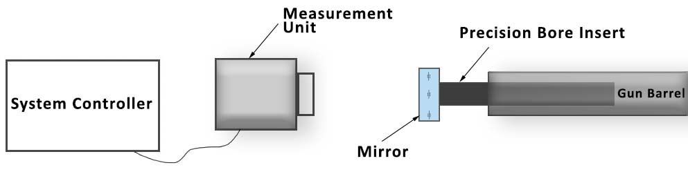
Figure 9a. A regular boresighting system schematic
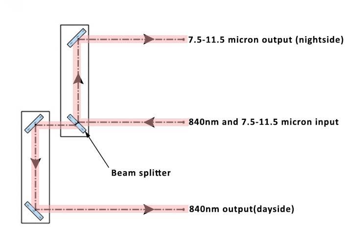
Figure 9b. PLX’s boresighting system schematic
Case Study: Satellite Onboard Boresighting
PLX’s boresighting technology can also be deployed for space-based applications. PLX designed and delivered two LTHRTM assemblies for the boresighting of the laser and receiver telescope for the ATLAS (Advanced Topographic Laser Altimeter System) program, aboard the ICESat-2 satellite. Each LTHRTM is a part of the Alignment Monitoring and Control System (AMCS). This is extremely critical as the return beam intensity is incredibly low. At the orbiting altitude, a slight mis-alignment could have the transmitter and receiver looking at different areas of the Earth’s surface. The ICESat-2 mission is designed to provide elevation data of the Earth’s surface, including information about ice sheet mass and vegetation canopy.
PLX Inc.
PLX can adapt its Boresighting and Boresighting Verification Technology to meet your specific new equipment or upgrade needs. For more targeted optical engineering solutions, call PLX at (631) 586-4190 or contact us.
Patents 7,168,817, 7,268,960, 8,851,689, 9,097,586 and Patents Pending