Hard-Mounted Hollow Retroreflectors™(HMHR)
- Invariant mirror configuration with extraordinary beam return accuracy.
- Mirrors can be coated for maximization over a spectral range, from UV to far IR.
- For critical applications, such as Michelson interferometers.
- Performs well in harsh environmental conditions.
- Custom "Knife Edge" design option available upon request, enhances beam quality, eliminates the cause of obscuration.
- RoHS Compliant.
- PLX is a registered ISO 9001 company.
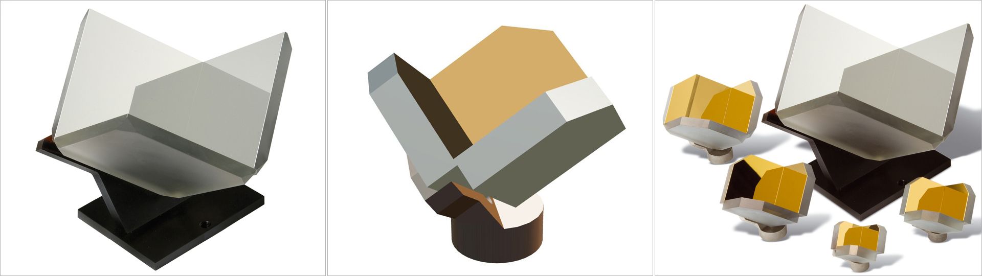
Hollow Retroreflectors
Light incident on the HMHR will be returned parallel to itself with great accuracy, regardless of the HMHR's physical orientation.
The HMHR is constructed of three first-surface mirrors assembled by a proprietary process into a mutually-orthogonal inside corner. The mirrors can be coated for maximization over a spectral range, from UV to far IR. This configuration eliminates material absorption and chromatic aberration. The mirror assembly of the HMHR is mounted on an Invar mount. (5.0"/127mm unit comes with aluminum mount). Invar is a low-expansion (CTE 0.75 ppm/°F) alloy of iron and nickel that is used when control of thermally-induced dimensional change is required.
Stability and Accuracy
The HMHR offers properties which make it especially suitable for critical applications, such as Michelson interferometers. The mount maintains stability of the distance between the apex of the corner cube and the back surface of the mount, as well as concentricity of the apex with respect to the mounting thread. HMHRs can also be provided in matched pairs for better modulation.
Coatings
Standard HMHR mirror coatings are aluminum, and gold, in both bare metal and with protective overcoats, and protected silver. All protected PLX coatings meet MIL-SPEC durability and adhesion requirements. Unprotected metallic coatings are especially suited to interferometric applications. Custom coatings available.
Custom configurations for specialized applications
PLX engineers can create a custom HMHR for your application. Potential variations include: smaller and larger apertures; modified hard mounts to meet your interface; super-critical accuracies; dielectric mirror coatings for high-powered lasers; and units able to withstand military and space environments.
| Specification Chart | ||||
|---|---|---|---|---|
| Model | Clear Aperture (in/mm) |
Beam Deviation (arc.sec.) |
Exiting Wavefront (p.v.633nm) |
Weight (grams) |
 HM-10
HM-10
|
1.0/25 | 0.5 - 30.0 | 0.10 - 3.50 | 25 |
 HM-15
HM-15
|
1.5/38 | 0.5 - 30.0 | 0.10 - 5.25 | 45 |
 HM-20
HM-20
|
2.0/50 | 0.5 - 30.0 | 0.15 - 7.00 | 90 - 110 |
 HM-25
HM-25
|
2.5/63 | 0.5 - 30.0 | 0.25 - 9.00 | 110 - 141 |
 HM-50
HM-50
|
5.0/127 | 0.5 - 30.0 | 0.45 - 18.0 | 551 - 780 |