Metrology System for Inter-Alignment of Lasers, Telescopes, and Mechanical Datum
By Oren Aharon, Duma Optronics Ltd
Co-author Itai Vishnia, PLX
ABSTRACT
In modern scientific and industrial laser applications, inter-alignment of multiple optical devices is frequently a basic requirement to meet a certain specification and performance.
However, the designed optical system combining mechanical elements, lasers and optical sights in various wavelengths frequently deviates from specified goals due to real life imperfections and effects. These may include mechanical tolerances, optical distortion, heating, laser cavity misalignment, overall instabilities, and non-linear effects.
In order to deliver accurately and produce intricate optical systems, a carefully designed method for interalignment is required completing and updating the already existing methods. Thus, we designed and upgraded the performance of an electronic autocollimator and combined it with innovative mechanical manipulation of optical invariants such as a Lateral Transfer Hollow Periscope to greatly improve and expand inter-alignment procedures.
Depending on the combination of optical sights, laser types, and mechanical requirements, an appropriate method will be analyzed. For example, several layouts will be analyzed such as high power CO2 laser cavity alignment, laser delivery system, and mechanical rollers alignment. By completing the presented gear in this article other instruments such as Align Meter, Lateral Hollow Periscope (LTHP™), Lateral Hollow Retroreflector (LTHR™) are available for applications such as alignment of articulated beam delivery systems.
This article will cover the aspects of laser beam and optical devices inter-alignment especially where parallax between elements poses a great challenge.
1. FUNDAMETALS OF INTER-ALIGNMENT GEAR
To avoid over-specifying mechanical and optical tolerances, it is helpful to use final alignment and assembly processes that can achieve high levels of accuracy and superior overall performance. The system’s assembly level should provide the engineer with the most appropriate assembly technique and instruments to perform the alignment task that will improve performance without the added cost of manufacturing of very accurate parts.
Advances in sensor technology have opened the door to a new measuring instrument, based on autocollimation principles combining laser beam collimation and direction measurement, accurate telescopic measurement, focusing techniques with sophisticated software and computing techniques.
1.1 Laser analyzing autocollimator
Of special interest is the laser analyzing autocollimator since it combines laser-analyzing technology with angular reflection technology.
The technology presented allows combining data of the alignment autocollimator with incoming laser beam information to increase the overall performance and possible applications. Laser beam deviation is compared with autocollimator center and allows intricate alignment of lasers and optical elements to mechanical datum planes.
Due to the above features, the proposed device is potentially usable in aligning a laser beam to its mirrors as well as the alignment of a laser cavity and laser rods.
Moreover, the demand for greater precision in high-performance applications, especially in high power CO2 laser systems for automotive industries, has increased the use of these lasers. As higher accuracies for mechanical alignment combined with higher power levels can be achieved, optical alignment is a necessity.
The autocollimator device comprises of two instruments fused into a single unit; one being an electronic autocollimator and the second is a laser beam profiling system. This combination with some additional optics is very useful in the alignment and angular analysis of lasers and optical devices.
1.2 Description of Laser Autocollimator
Known autocollimators are high-precision instruments for measurement of angular reflections. Main applications are calibration and measurement tasks in optical and mechanical engineering.
An autocollimator projects a reticle pattern as a collimated beam to infinity by a telescopic lens. A mirror positioned in its optical path reflects the beam into the autocollimator’s aperture.
The reflected beam generates the autocollimation image that is observed by the user via an eyepiece. In general, the autocollimation effect and name are derived from the fact that the same telescopic lens is used to both project the image and collect its back reflection from a mirror element.
The shift of the autocollimation image from the center of the reticle in both an x and y direction is proportional to the mirror’s tilt angle. An electronic autocollimator presents the angular deviation using CCD cameras with resolutions down to 0.01 arc sec. For increased capabilities, a new breed of autocollimators was designed with built-in laser beam profiling for analyzing incoming collimated beams for measuring divergence and incoming angle with respect to autocollimator’s center. Moreover, by a builtin focusing knob, accurate center position of mechanical systems is possible.
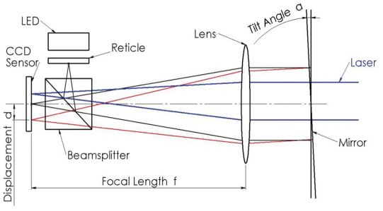
Figure 1: Principals of Electronic Autocollimator
1.3 Lateral Offset Device (LOD)
The uniqueness of the Lateral Offset Device is that it can cancel the parallax between several lines of sights over an almost continuous distance. The LOD (Fig. 2) illustrates two Rotary Mounts orthogonally mounted with respect to each other and a Hollow Periscope fixed to the top Rotary Mount. The orthogonally mounted Rotary Mounts' purpose is to steer the periscope mounted on the top Rotary Mount. By doing so, the distance between an incoming light beam into the periscope and its outgoing direction is controlled.
Due to the above features, the proposed device is potentially usable for alignment or Boresighting between two parallel lines of sights or laser beams as well as the alignment of mechanical datum planes relative to other optical devices.
The Monolithic Hollow Periscope is based on two parallel mirrors with a given distance in between. The Rotary Mount is preferably mounted on a mechanical device serving as an optical bench.
For further understanding of the complexity of inter-alignment, the characteristics of several applications are to be described, namely: High power CO2 laser cavity alignment, testing accuracy of a beam delivery system and testing parallelism of rollers for mechanical processing.
Combining the laser analyzer autocollimator with an LOD opens the door to numerous intricate alignments that would otherwise be quite difficult and time consuming to produce.
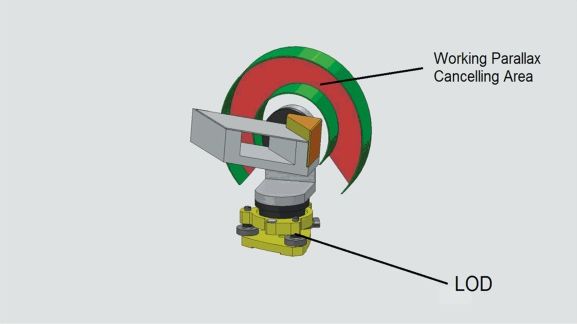
Figure 2: Lateral offset device
2. HIGH POWER CO2 LASER CAVITY ALIGNMENT
There are many CO2 laser cavities configurations, however, we will concentrate our attention on high power applications where several tubes are working together with one resonator, and the laser beam is directed using folding mirrors.
Typical outputs are 600 W per meter of cavity length, with total laser beam outputs available up to 6 kW. Extending the length of the laser cavity is achieved by cascading several tubes along the laser cavity; folding the cavity using mirrors allows relatively compact CO2 laser to be built. Commercial CO2 lasers that use six tubes (and ten turning mirrors) are available and achieve high power output. The following image describes the working principle of CO2 lasers and typical folding configurations; 3D folding configurations can also be used.
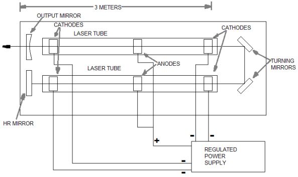
Figure 3: Axial Flow CO2 laser
Figure 3 above shows the preferred method of achieving an extended active length while minimizing overall dimensions and power supply cost. The optical cavity is folded once to utilize two plasma tubes positioned side by side. This is a relatively simple configuration, however, the same principles are applicable for more complicated cavities with multiple three dimensional foldings.
Proper alignment of an optical cavity especially if folded is crucial. The laser beam and the optical cavity axis should completely coincide. It is critical that the laser beam couples completely to the fundamental (longitudinal) spatial mode of the cavity and not at all to the higher-order (off-axis) spatial modes. A transverse displacement or angular mismatch between the laser beam and the cavity can have an unwanted effect on the total beam power and its modes. By imposing strict alignment procedures, those effects can be minimized. Furthermore, alignment to mechanical datum improves production repeatability and downtime costs in case of laser replacement. The main alignment goals are as follows:
- Alignment of laser tubes to each other and mechanical datum
- Alignment of folding mirrors
- Alignment of pointing visible laser and cavity mirrors.
The following 3D solid drawing (Figure 4) shows the necessary layout. We start by aligning the autocollimator to the mechanical datum by directing its line of sight to the reflective datum by using the pan and roll features of LOD. Next, by using the mounted V-blocks on the laser tubes, we align the tubes to be parallel to each other and mechanical datum. This is further achieved by the LOD device shifting the autocollimator’s line of sight to the reflective elements mounted on top of the CO2 tubes and adjusting the tubes accordingly. An external laser can also be adjusted to the same line of sight and projected through the first tube towards the folding mirrors, enabling adjusting the folding mirrors until perfect parallelism between incoming and returned beam is achieved.
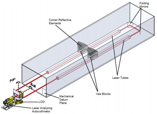
Figure 4: Alignment of laser cavity using laser-analyzing autocollimator
3. LASER BEAM DELIVERY SYSTEM
There are different configurations of industrial laser cutting machines: moving material, hybrid, and flying optics systems. These refer to the way that the laser beam is moved over the material to be cut or processed. For all of these, the axes of motion are typically designated as X and Y axis. If the cutting head may be controlled, it is designated as the Z-axis.
Flying optic machines must use some method to take into account the changing beam length from a near field cutting (close to resonator) to a far field cutting (far away from resonator). Common methods for controlling this include collimation, adaptive optics or the use of a constant beam length axis.
Characterizing factors for all flying optics systems is that the laser is stationary, and the beam is delivered by mirrors after a long path.
Five and six-axis machines also permit cutting formed workpieces. Also, there are various methods of orienting the laser beam to a shaped workpiece, maintaining a proper focus distance and nozzle standoff.
On flying optics machines, even minute changes in beam direction relative to the working table can cause large positional deviations due to the laser’s long path. In other words, the deviation (D) is directly proportional to the angular deviation (A) multiplied by total path travel (T).
D = (A) x (T)
-where D is the deviation,
-A is the angular deviation,
-T is the total path travel
Thus, examining beam angle variations across the working table is a very important feature, crucial for total accuracies in material processing by flying optics methods.
Figure 5. Here again, using the same basic instrumentation in a somewhat different configuration, we sample the beam direction as it hits the work area at several positions using the LOD and the laseranalyzing feature of the autocollimator.
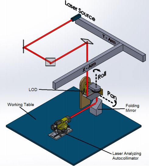
Figure 5: Examining beam angles on a working table
After examination the focused laser beam will strike the material with perfect accuracy. The laser beam moves along the part contour, melting or welding as it goes.
4. ADJUSTMENT OF MECHANICAL PARALLEL ROLLERS
Materials such as paper, plastic film, newspaper, wide bed printers, foil and metal sheets are often produced in long machines with multiple parallel rolls. These rolls are usually mounted on accurate bearings and are parallel to each other, having a significant alignment requirement regarding the parallelism between rollers. Parallel rollers prevent skewing of processed material as it passes through the processing path. Measurement of parallelism alignment of rolls is often impossible while the machine is processing the material.
Many companies need to check parallelism in-situ and as a preventive maintenance procedure. On completion of the measurement, a roller adjustment can be applied if required. Alternatively, the rolls may be replaced or overhauled depending on manufacturers specifications.
A new method of performing in-situ measurements is presented as follows, where the measurement is performed by attaching a reference mirror to the end point of the rollers axis as shown in the schematic below. The mirror rotation is observed by the autocollimator through reflection; the reflected beam draws a perfect circle having a center coinciding with the axis direction of the rollers. By using the adjustable LOD the line of sight of the autocollimator can be moved from one roller to another. Perfect alignment is achieved when all circles generated by the rollers’ end tip have the same center.
Furthermore, if the circle generated by the rollers is not perfect or wobbles, this can be easily spotted by the autocollimator and LOD. Rollers alignment is an important part of machine operation; a non-aligned device has a tendency to track off course and wander out of alignment during the processes. To avoid these problems, measurement and maintenance are crucial.
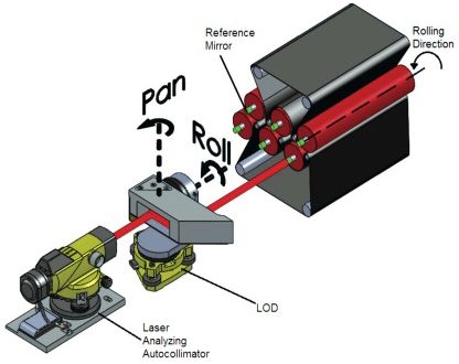
Figure 6: In-situ measurement of rollers misalignment
Automatic measurement based on these principles can yield web-guiding systems to be positioned just before a critical stage on a converting machine (for example, just before print station).
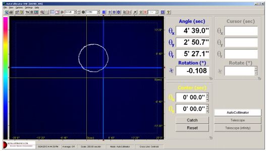
Figure 7: Sample screen showing the rollers misalignment
Center of traced circle (Figure 7) is exactly at the center of rotation of one of the rollers. Perfect alignment of rollers' parallelism is when all reflected-traced centers have the same center.
SUMMARY OF CONCLUSIONS
This article covers various aspects of the laser beam and optical devices’ inter-alignment, especially where parallax between elements has to be canceled to perform the task.
The alignment is based on a technological fusion of several instruments such as an electronic Autocollimator, laser beam profiler, optical invariants and sophisticated, innovative mechanics combined with sophisticated algorithms. The innovative LOD is capable of shifting the autocollimator’s line of sight over a large area while maintaining perfect parallelism between incoming and outgoing directions.
This means that various applications in areas such as Boresighting, industrial alignment, laser cavity manufacturing and other numerous areas are now possible. Of special interest could be an application of segmented optical dish used for solar concentrators. Here the optical dish being very large is manufactured from segments; assembled inter- alignment between segments is crucial. Although beyond the scope of this article, it seems an interesting application. Finally, it was also shown that a mechanical application for accurate inter-alignment of mechanical parts is also feasible offering higher accuracies and even measurements that otherwise would be quite difficult to perform.
The results of this article are particularly suited to help designing future alignment and procedures for high power laser cavity, especially in the CO2 lasers applications.
Footnotes
Oren Aharon, CTO, Duma Optronics Ltd., email: oren@duma.co.il, website: www.duma.co.il
Itai Vishnia, COO, PLX Inc., email: iv@plxinc.com, website: www.plxinc.com